
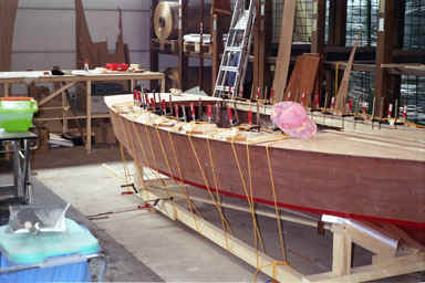
Between fore and aftdeck the pieces of my false floor are placed for drying after their first coat of 2c-PU varnish.
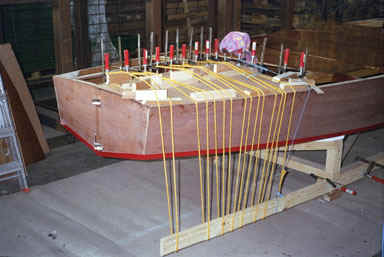
Finally, having completed all (?) works on the inside, I was ready to mount the deck pieces.
As I didn't have sheets at hand that would cover the total width of front or aft deck, I needed to mount them in two halves connected mid-ships. Fortunately all sheets were out of the same production and had similar veining, so could arrange the individual sheets until I was satisfied with the optical impression.
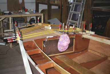
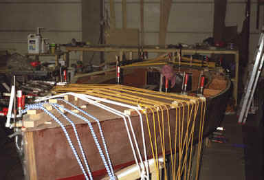
Rope wise of course this part of the job was again a challenge, but bowline, rolling hitch and the others helped a great deal.
All inner surfaces of course received an epoxy layer using the FLOW-COAT method.
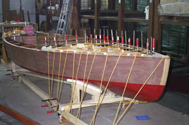
Die edges where fore and aft decks meet the side decks were carefully prepared with a plane to care for minimum gaps. near the gaps I used epoxy thicked with brown spheres - for optical reasons.
Finally - again for optical reasons - I made an inlay of oak in the midship line of the foredeck.
A truley exciting moment
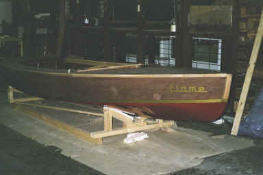
The logo and waterline hull-line were made by a professional using gold colored adhesive. This adhesive looks very disappointing in its original, but the expert confirmed that, once the varnish was on, it would shimmer like the crown jewels. Let's wait & see ...
... he was right!
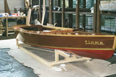
Here we see FLAME after layer four.
The complete sequence was:
The sandings - you guessed it already - mark the pauses between two weekends where I could not stick to the paint-over times. I also had to remove small particles which are not totally avoidable in this kind of environment, no matter how carefully you are.
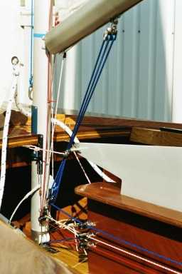
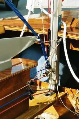
front view of centerboard case - port side
Main - downhaul (blue)
Main - clew outhaul (white)
Main - luff downhaul (a.k.a. Cunningham - red)
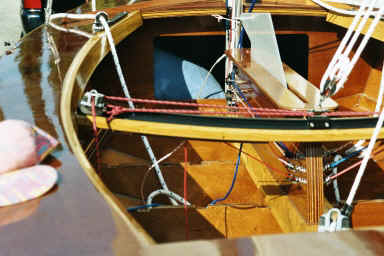
front view of centerboard case - starboard side
centerboard hoist (white/red)
Spi - topping lift (blue)
Spi - halyard (red)
view towards bow, port side
Traveller - triplines (red/blue)
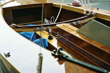
view towards stern, starboard side
all important cleats are mounted on the front side of the traveller
Mounting the fittings needed to be carefully planned. You want to have it cosy - not too much stuff, but definitely not too few functionality.
It is rather interesting how your viewpoint about "bare minimum" changes over time.
And my guess, that the mast would be the last "big" spending had to be revised, too - even though I spent days digging through catalouges, internet sites etc.
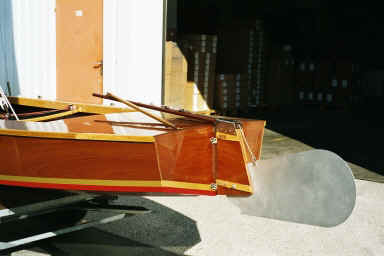
In the very shallow waters of Neusiedlersee a rudder that can be lifted is of big advantage. This year (2003) we have an exceptionally low water level.
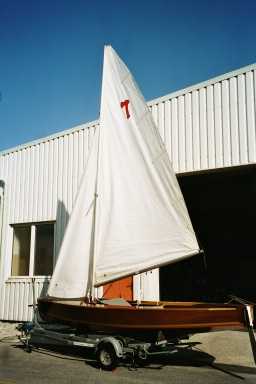
Testing how the sails fit:
Setting the main is (still) quite a heavy task, because the touring sail has a thicker leech line as state-of-the-art racing sails.
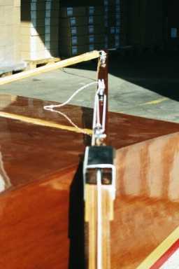
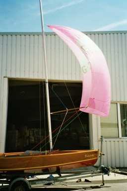
The Spi topping lift is redirected into the cockpit via a sheave. The counter force is applied by an elastic strop running between spi pole and deck.
